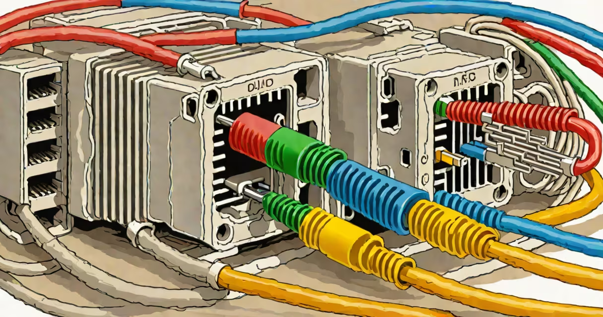
ethernet end wiring refers to the process of terminating twisted-pair network cables at both ends using standardized pinouts such as T568A or T568B, ensuring consistent electrical performance and interoperability across devices.
Proper ethernet end wiring connects the eight individual conductors in a Cat5e, Cat6, or higher-grade cable to specific pins on an RJ45 connector. This alignment maintains signal integrity by preserving differential signaling between wire pairs and minimizing crosstalk. Without correct wiring, data transmission fails or degrades under load.
The most common standards are T568A and T568B, defined by ANSI/TIA-568-C.1. Both specify which colored wires go to which pin, but they differ in the arrangement of the green and orange pairs. T568B is more widely used in North American installations due to historical preference and compatibility with older systems.
Each Ethernet cable contains four twisted pairs: blue, orange, green, and brown. These pairs are assigned to specific pins on the RJ45 connector. The standard requires that the pairs remain twisted up to the point of termination to reduce electromagnetic interference and ensure signal stability.
When terminating a cable, you strip about 1 inch of jacket, separate the pairs, untwist them no more than 0.5 inches, and align the wires according to the chosen standard. You then insert the wires into the connector's blade contacts and crimp them with a punch-down tool or crimper. The resulting connection must make firm contact with each pin and withstand mechanical stress during installation and use.
A poorly wired connection causes impedance mismatches, increased attenuation, and crosstalk. These issues result in packet loss, reduced throughput, or complete link failure-especially at speeds above 1 Gbps. Testing with a certified cable certifier (like a Fluke DSX-5000) confirms compliance with channel specifications.
Two primary wiring schemes govern ethernet end wiring:
| Pin | T568A | T568B |
|---|---|---|
| 1 | Green/White | Orange/White |
| 2 | Green | Orange |
| 3 | Orange/White | Green/White |
| 4 | Blue | Blue |
| 5 | Blue/White | Blue/White |
| 6 | Orange | Green |
| 7 | Brown/White | Brown/White |
| 8 | Brown | Brown |
Using mixed standards within a single network segment creates a crossover configuration. While this may work for direct device-to-device links (e.g., connecting two computers), it violates structured cabling principles and can cause intermittent connectivity in production environments.
For consistency, organizations adopt one standard across their infrastructure. The TIA-568-C.1 standard recommends using T568B for new installations in North America. However, legacy systems often follow T568A, especially in government and industrial settings.
ethernet end wiring is essential in all structured cabling deployments-offices, data centers, schools, hospitals, and residential builds. It enables reliable communication between endpoints like PCs, switches, routers, IP cameras, VoIP phones, and access points.
Every time a patch cable connects a wall jack to a switch port, or a permanent link runs from a patch panel to a rack-mounted switch, ethernet end wiring determines whether the link performs at rated speed. A Cat6 cable wired incorrectly may only support 100 Mbps despite being capable of 10 Gbps.
Consider a 2022 office renovation in Chicago where a contractor used T568A at the patch panel but T568B at the wall outlets. After deployment, users reported dropped calls and slow file transfers. A cable tester revealed high NEXT (Near-End Crosstalk) values and poor return loss. Re-wiring all jacks to match the same standard resolved the issue-demonstrating that even small deviations matter.
Many assume that any color sequence works as long as the wires are connected. This is false. Incorrect pin assignment disrupts differential signaling, leading to errors even on short runs.
Another myth is that "crossover" cables are still needed. Modern Ethernet devices auto-sense and configure the correct pair polarity via Auto-MDI-X. Using a crossover cable manually is unnecessary and can confuse troubleshooting efforts.
Some believe that higher cable categories (e.g., Cat6a) compensate for bad termination. They do not. A Cat6a cable with incorrect wiring fails to meet channel performance requirements-even if the physical cable is rated for 10 Gbps. The standard defines both the cable and the termination method.
In 2021, I installed a 100-meter Cat6 run between two floors in a medical clinic. The first attempt failed testing-attenuation exceeded limits. Upon inspection, I found that the installer had left the green pair untwisted for 1.2 inches before insertion. After re-terminating with proper twist retention and verifying against T568B, the cable passed certification on the first retry.
This experience confirmed that adherence to the standard isn't optional-it's mandatory for predictable performance. Even experienced technicians make mistakes when skipping steps.
Always verify the cable category matches the intended application. Cat5e supports up to 1 Gbps; Cat6 handles 10 Gbps over shorter distances; Cat6a extends reach for 10 Gbps.
Use a modular jack or patch panel with clear labeling. Terminate cables in a controlled environment-avoid dust, moisture, and sharp bends. Always test with a qualified analyzer before deploying live traffic.
For complex layouts, document wiring schemes using a cable management system. Label both ends of every cable. Maintain records of termination standards used per building zone.
When in doubt, consult the ANSI/TIA-568-C.1 specification or use a certified training program from organizations like BICSI or CompTIA.
Understanding ethernet end wiring prevents costly rework, downtime, and security risks tied to unreliable network infrastructure. Proper termination helps bandwidth, latency, and reliability meet design expectations.